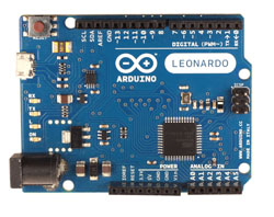
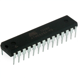
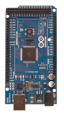
Arduino Mega is based on ATmega2560 microcontroller. The board has 54 digital I/Os (14 of which can be used as PWM outputs), 16 analog inputs, 4 serial UART ports, a 16 MHz crystal oscillator, USB connector, power connector, ICSP header, and a reset button. To work, you need to connect the platform to the computer using a USB cable or supply power using an AC/DC adapter or a rechargeable battery. Arduino Mega 2560 is compatible with all expansion boards designed for platforms Uno or Duemilanove.
Schematic and raw data
EAGLE files: arduino-mega2560-design.zip
Circuit diagram : arduino-mega2560-schematic.pdf
Brief characteristics
|
Microcontroller |
ATmega2560 |
|
Operating voltage |
5V |
|
Input voltage (recommended) |
7-12V |
|
Input voltage (limit) |
6-20V |
|
Digital I/O |
54 (14 of which can act as PWM outputs) |
|
Analog inputs |
16 |
|
DC current through I/O |
40 mA |
|
DC current for 3.3V output |
50 mA |
|
Flash memory |
256 KB (of which 8 KB is used for bootloader) |
|
RAM |
8 KB |
|
Non-volatile memory |
4 KB |
|
Clock speed |
16 MHz |
Power
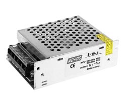
The Arduino Mega can be powered via USB or external power. The power supply is automatically selected.
External power (not USB) can be supplied via an AC/DC converter (power supply) or battery. The voltage converter is connected via a 2.1 mm plug with a positive pole at the center contact. The battery wires are connected to the Gnd and Vin pins of the POWER connector.
The platform can operate with an external power supply from 6V to 20V. If the supply voltage is below 7V, the 5V pin may supply less than 5V, and the platform may be unstable. When using voltages above 12V, the voltage regulator may overheat and damage the board. The recommended range is 7V to 12V.
The Mega2560 board, unlike previous board versions, does not use an FTDI USB microcontroller. For data exchange via USB, an Atmega8U2 microcontroller is used, programmed as a USB-to-serial converter.
Power pins:
-
VIN. The input is used to supply power from an external source (in the absence of 5V from a USB connector or other regulated power supply). The supply voltage is supplied through this pin. If power is supplied to the 2.1mm connector, then this input can be powered.
-
5V. A regulated voltage source used to power the microcontroller and components on the board. Power can be supplied from the VIN pin via a voltage regulator, or from a USB connector or other regulated 5V voltage source.
-
3V3. 3.3V pin voltage generated by the FTDI chip on the platform. Maximum current consumption 50 mA.
-
GND. Ground pins.
Memory
The ATmega2560 microcontroller has: 256 KB of flash memory for storing program code (4KB is used for storing bootloader), 8KB RAM and 4KB EEPROM (which is read and written by EEPROM library ).
Inputs and Outputs
Each of the 54 digital pins of the Mega, using the functions pinMode(), digitalWrite(), and digitalRead(), it can be configured as an input or an output. The pins operate at a voltage of 5 V. Each pin has a pull-up resistor (disabled by default) of 20-50 kΩ and can pass up to 40mA.Some pins have special functions:
-
Serial: 0 (RX) and 1 (TX); Serial 1: 19 (RX) and 18 (TX); Serial 2: 17 (RX ) and 16 (TX); Serial bus 3: 15 (RX) and 14 (TX). Pins are used to receive (RX) and transmit (TX) TTL data. Pins 0 and 1 are connected to the corresponding pins of the ATmega8U serial bus 2.
-
External interrupt: 2 (interrupt 0), 3 (interrupt 1), 18 (interrupt 5), 19 (interrupt 4), 20 (interrupt 3), and 21 (interrupt 2). These pins can be configured to trigger an interrupt on either a low value, a rising or falling edge, or when the value changes. See attachInterrupt () for details.
-
PWM: 0 to 13. Any of the pins provide 8-bit PWM using the function analogWrite().
-
SPI: 50 (MISO), 51 (MOSI), 52 (SCK), 53 (SS). Via these pins are made by SPI communication, for example using the SPI library . Also, SPI pins can be output to the ICSP block, which is compatible with Uno, Duemilanove and Diecimila platforms.
-
LED: 13. Built-in LED connected to digital pin 13. If the pin is high, the LED is on.
-
I2C: 20 (SDA) and 21 (SCL). Pins provide I2C (TWI) communication. Wire library (information on the Wiring website) is used for creation. The pin layout on the Mega platform does not match the layout of the Duemilanove or Diecimila.
The Mega2560 platform has 16 analog inputs, each with a resolution of 10 bits (ie, it can accept 1024 different values). The pins have a range of up to 5V relative to ground as standard, however, it is possible to change the upper limit using the AREF pin and analogReference () function.
Additional pair of platform pins:
-
AREF. Voltage reference for analog inputs. Used with function analogReference().
-
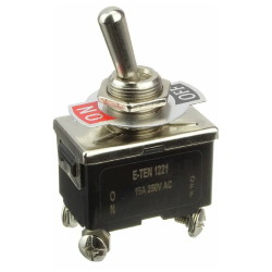
Reset. A low pin level reboots the microcontroller. Usually used to connect a reset button on an expansion board, which prevents access to the button on the Arduino board itself.
Communication
The Arduino Mega2560 platform has several devices installed to communicate with a computer, other Arduino devices, or microcontrollers. The ATmega2560 supports 4 UART serial communication ports for TTL. The ATmega8U2 microcircuit installed on the board directs one of the interfaces via USB, providing a virtual COM port to programs on the computer (Windows machines need an .inf file to work correctly with a virtual COM port, OSX and Linux systems will automatically recognize the COM port). The Serial Monitor utility of the Arduino development environment allows you to send and receive text data when connected to the platform. The RX and TX LEDs on the platform will flash when transmitting data through the ATmega8U2 and USB connection (but not when using serial communication on pins 0 and 1).
With the library SoftwareSerial it is possible to create serial data transmission via any of the digital pins of the Mega2560.
The ATmega2560 supports I2C (TWI) and SPI interfaces. The Arduino includes a Wire library for easy use of the I2C bus. More information is available on the website Wiring. For SPI communication, SPI library .
Programming
The platform is programmed using the Arduino development environment. For more information, see the manual and instructions .
The ATmega2560 microcontroller comes with a pre-recorded bootloader, making it easy to write new programs without using external programmers. Communication is carried out by the original STK500 protocol.
It is possible not to use the bootloader and program the microcontroller through the ICSP block pins (in-circuit programming). Details are in this manual .
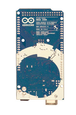
Firmware code for ATmega8U2 controller available for free download . The ATmega8U2 controller has its own DFU bootloader, which can be activated by closing the jumper on the back of the board (next to the Italy map) and rebooting the controller. To write new firmware it is possible to use Atmel's FLIP (under Windows) or DFU programmer (on Mac OS X or Linux). You can also rewrite the firmware with an external programmer using ISP input.
Automatic (software) reboot
Mega is designed in such a way that before writing a new code, the reboot is carried out by the program itself, and not by pressing a button on the platform. One of the ATmega8U2 data flow control (DTR) lines is connected to the reset pin of the ATmega2560 microcontroller via a 100nF capacitor. Activation of this line, i.e. giving a low level signal, reboots the microcontroller. The Arduino program, using this function, uploads the code with one click of the Upload button in the programming environment itself. The low-level signaling on the DTR line is coordinated with the start of the code recording, which reduces the bootloader timeout.
This function has another application. The Mega2560 reboots every time it is connected to the Arduino program on a Mac X or Linux computer (via USB). The bootloader works for the next half second after the reboot. During programming, the first few bytes of the code are delayed to prevent the platform from receiving incorrect data (all except the code of the new program). If you perform a one-time debugging of a sketch written to the platform, or enter any other data at the first start, you need to make sure that the program on the computer waits for a second before transferring data.
On Mega2560 it is possible to disable the automatic reload line by breaking the corresponding line. The pins of the microcircuits at both ends of the line can then be connected for recovery purposes. The line is marked "RESET-EN". It is also possible to disable automatic reboot by connecting a 110 Ohm resistor between the 5 V supply and this line.
Current protection of the USB connector
The Arduino Mega2560 has a built-in reloadable fuse that protects the computer's USB port from short currents short circuits and overcurrents. Although virtually all computers have this type of protection, this fuse nonetheless provides an additional barrier. The fuse automatically interrupts communication when a current of more than 500 mA passes through the USB port.
Physical characteristics and compatibility with expansion cards
The length and width of the Mega2560 PCB are 10.2 and 5.3 cm, respectively ... USB and power connectors are outside of these dimensions. Three holes in the board allow it to be fixed to a surface. The distance between digital pins 7 and 8 is 0.4 cm, although it is 0.25 cm between the other pins.
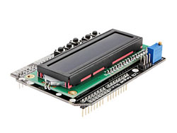
Arduino Mega2560 is compatible with all expansion boards designed for Uno, Duemilanove or Diecimila platforms. The layout of pins 0-13 (and adjacent AREF and GND), analog inputs 0-5, power connector, ICSP block, UART serial port (pins 0 and 1) and external interrupt 0 and 1 (pins 2 and 3) on the Mega corresponds to location on the platforms above. SPI communication can be done through the ICSP block on both Duemilanove/Diecimila and Mega2560 platforms. However, the pinouts (20 and 21) of the I2C communications on the Mega platform do not match the pinouts (analog inputs 4 and 5) on the Duemilanove/Diecimila.


 The data presented in the product description are for reference only and may differ from those indicated by the manufacturer.

.jpg)