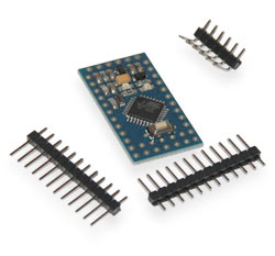
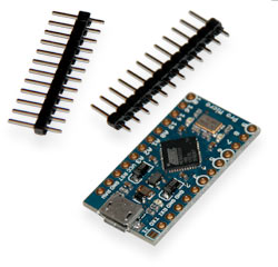
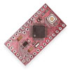
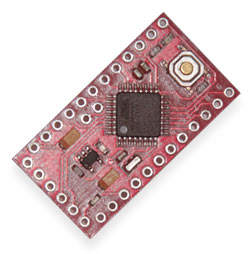
Arduino Pro Mini is based on ATmega168 or ATmega328 microcontroller. The platform contains 14 digital inputs and outputs (6 of which can be used as PWM outputs), 6 analog inputs, a resonator, a reset button and holes for pin mounting. The six-pin block can be connected to an FTDI cable or Sparkfun converter board to provide power and USB communications.
The Arduino Pro Mini is designed for non-permanent installation in objects or exhibits. The platform is shipped with no pins installed, allowing users to use their own pins and connectors. The pinout is compatible with the Arduino Mini platform.
There are two versions of the Pro Mini platform. One version operates at 3.3V @ 8MHz, the other @ 5V @ 16MHz.
Arduino Pro Mini is designed and manufactured by SparkFun Electronics.
Schematic and background
EAGLE files: arduino-pro-mini-reference-design.zip
Schematic diagram: Arduino-Pro-Mini-schematic.pdf
Characteristics
|
Microcontroller |
ATmega168, ATmega328 |
|
Operating voltage |
3.3V or 5V (depending on model) |
|
Input voltage |
3.35-12V (3.3V model) or 5-12V (5V model) |
|
Digital I/O |
14 (6 of which can be used as PWM outputs) |
|
Analog inputs |
6 |
|
DC current through I/O |
40mA |
|
Flash memory |
16KB (2 used for bootloader) |
|
RAM |
1KB |
|
EEPROM |
512 bytes |
|
Clock |
8 MHz (3.3V model) or 16 MHz (5V model) |
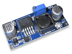
Power supply
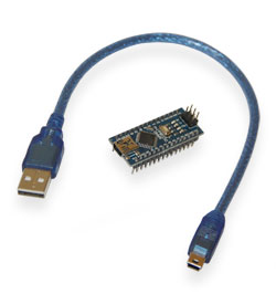
Arduino Pro Mini can be powered: via From an FTDI cable, or from a converter board, or from a regulated 3.3V or 5V power supply (depending on the platform model) via the Vcc pin, or from an unregulated source via the RAW pin.
Power pins:
-
RAW. To connect unregulated voltage.
-
VCC. For connecting 3.3V or 5V regulated.
-
GND. Ground pins.
Memory
The ATmega168 microcontroller has: 16 KB flash memory for storing program code (2 KB used to store the bootloader), 1 KB RAM and 512 bytes EEPROM (which is read and written using the EEPROM library ).
Inputs and Outputs
Each of 14 digital Pro pins, using the functions pinMode(), digitalWrite(), and digitalRead(), can be configured as input or output. The pins operate at 3.3 V. Each pin has a pull-up resistor (disabled by default) 20-50 kΩ and can pass up to 40 mA.Some pins have special functions:
-
Serial bus: 0 (RX) and 1 (TX) . The pins are used for receiving (RX) and transmitting (TX) TTL data. These pins are connected to the TX-0 and RX-1 pins of the six-pin block.
-
External interrupt: 2 and 3 . These pins can be configured to trigger an interrupt on either a low value, a rising or falling edge, or when the value changes. See attachInterrupt () for details.
-
PWM: 3, 5, 6, 9, 10, and 11 . Either pin provides 8-bit PWM using the analogWrite().
-
SPI: 10 (SS), 11 (MOSI), 12 (MISO), 13 (SCK) function. These pins provide SPI communication which, although supported by the hardware, is not included in the Arduino language.
-
LED: 13. Built-in LED connected to digital pin 13. If the pin is high, the LED is on.
The Pro Mini platform has 6 analog inputs, each with a resolution of 10 bits (i.e., it can accept 1024 different values). Four of them are located at the edge of the platform, while the other two (entrances 4 and 5) are closer to the center. The measurement is relative to ground to the VCC value. Some pins have additional functions:
-
I2C: 4 (SDA) and 5 (SCL) . The pins provide I2C communication (TWI) using the Wire library.
There is an additional pin on the platform:
-
Reset. A low signal level at the pin reboots the microcontroller. Usually used to connect a reset button on an expansion board, which prevents access to the button on the Arduino board itself.
Pay attention to the connection between Arduino pins and ATmega168 ports .
Communication
The Arduino Pro Mini platform contains several devices for communicating with a computer, other Arduino devices or microcontrollers. The ATmega168 supports UART TTL serial interface via pins 0 (RX) and 1 (TX). The Serial Monitor of the Arduino software allows you to send and receive text data over a USB connection.
The SoftwareSerial library allows you to create serial data transmission over any of the Pro Mini's digital pins.
ATmega168 supports I2C (TWI) and SPI interfaces. The Arduino includes a Wire library for easy use of the I2C bus. More details are in the documentation. To use the SPI interface, refer to the ATmega168 microcontroller datasheet.
Programming
The platform is programmed using Arduino software. More information can be found in the reference and instructions.
The ATmega168 microcontroller comes with a pre-recorded bootloader, making it easy to write new programs without using external programmers. Communication is carried out by the original STK500 protocol.
It is possible not to use the bootloader and program the ATmega168 using an external programmer. Please refer to this manual for details.
Automatic (software) restart
The Arduino Pro Mini is designed so that a reboot is done by the program itself before writing a new code, and not by pressing a button on the platform. One of the pins on the six-pin block is connected to the reset line of the ATmega168 microcontrollers via a 100nF resistor. This pin is connected to one of the flow control lines of the USB-to-serial converter connected to the unit: to the RTS lines when using the FTDI cable or to the DTR line when using the Sparkfun converter board. Activation of this line, i.e. giving a low level signal, reboots the microcontroller. The Arduino program, using this function, uploads the code with one click of the Upload button in the programming environment itself. The low-level signaling of the reset line is coordinated with the start of the code writing, which shortens the bootloader timeout.
This function has another application. The Pro Mini reboots every time it is connected to the Arduino program on a Mac X or Linux computer (via USB). The bootloader works for the next half second after the reboot. During programming, the first few bytes of the code are delayed to prevent the platform from receiving incorrect data (all except the code of the new program). If you are debugging a sketch written to the platform one-time, or entering any other data at the first start, you need to make sure that the program on the computer waits for a second before transferring data.
Physical characteristics
The dimensions of the Pro Mini PCB are 1.8 x 3.3 cm.


 The data presented in the product description are for reference only and may differ from those indicated by the manufacturer.
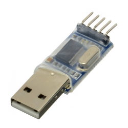
.jpg)